This article collects Builder Technical Support answers on wiring, harnesses and instrument panel.
18-gauge wire in a 20–24 gauge pin
If you find that 18-gauge power or ground wires in your harness have been trimmed to fit a 20–24 gauge pin, that is not acceptable for a power or ground circuit. Contact the harness supplier for a repair or a properly-sized pin. Do not fly the airframe with undersized pin terminations on power circuits.
Who It Applies To
SB-00036 applies to a range of RV models including the RV-6, -6A, -7, -7A, -8, -8A, and the RV-4 (cross-referenced with SB 14.1.31 and SB 14.2.05 for international applicability). Check the bulletin's applicability section against your serial number and aircraft configuration before assuming you are or are not affected.
Timing: Before or After Paint?
If your aircraft has not flown yet and is not yet painted, complying with SB-00036 before paint is the practical choice — opening up the area later means repainting. Re-read the bulletin's wording on inspection timing to confirm.
Builder Tech Support notes
How Builder Tech Support reads SB-00036: if there are no cracks, you can monitor the area yearly, or install the external doubler. If there are cracks within the criteria the bulletin gives, install both the internal and external doublers. Always follow the official Service Bulletin and contact Builder Tech Support before deciding on a repair.
Finding the right switch
For DPDT (double-pole double-throw) toggle switches in the 2-10 family, check the Van's store under switches and circuit protection. If you can't find a specific configuration on the store, email Builder Tech Support with the function (momentary, on-off-on, etc.) and they'll point you to the right part number.
Overview
Drilling out rivets and ending up with enlarged or elongated holes is one of the most common situations Builder Tech Support sees on wings, ribs, and spars. Here's how to think through the standard fixes and when to escalate.
WH-P30 vs. WH-P30-1 trim wire (RV-12 to RV-12iS conversion)
If you started an RV-12 empennage and are completing as RV-12iS, the trim wire harness changes. Contact Builder Support with your customer number and current part numbers and we'll confirm which harness you need.
When to replace
Replace any skin with cracks, dimple errors that cannot be reversed, or transport damage on a load-bearing flange. Cosmetic dings on flat skin areas can usually stay.
Overview
This article answers the most common questions about Van's drawings, KAI documents, and finding called-out parts - especially for builders on older or transitioning kits.
RV-12 to RV-12iS transitions
If you bought a Legacy RV-12 kit years ago and are completing as RV-12iS, expect plan and parts deltas - access panel changes, trim wire harness changes, and avionics installations are the common ones. The 42D section (avionics) has the heaviest changes.
FAB kit upgrades to current spec
For builders returning to a long-paused build and upgrading an older FAB (Front Air Box) kit to current spec, the current revision instructions cover the upgrade but don't always list every superseded part number. Common items requiring identification: VA-130-B top plate (legacy) vs current part, and adjacent hose and clamp updates. Contact Builder Tech Support with your kit revision date and current FAB part numbers for the full upgrade list.
Bolt hole damage from forcing fasteners
If you've galled wing or center-section bolt holes by forcing close-tolerance bolts through misaligned parts, do not continue. Send photos and a description to Builder Tech Support - depending on the location and degree of damage, the resolution may range from re-reaming to oversize hardware to a part replacement.
Plans revisions removing wires
When a plans revision (e.g., Page 10-25 Rev 2) removes a wire callout but the wire is still present in your harness or coming out of an existing component (L1082, CA1OP, etc.), the revision generally reflects a wiring change that applies to newer kits. For builders with the older harness, follow the revision where you can and tape off any orphaned wires. Confirm with Builder Tech Support before cutting wires in an existing harness.
Overview
If you're planning an instrument panel upgrade, sourcing a blank panel, or mounting avionics in a tight space, this article covers the recurring questions Builder Tech Support sees from RV builders.
Blank panels by model
Van's stocks blank panels for current kits including the RV-7A and RV-14. The blank panel is a pre-cut piece of aluminum shaped to fit the panel cutout - it is not pre-drilled for instruments. RV-4 panel availability varies; contact Van's parts for current stock.
Overview
If you're seeing cracks at dimpled holes, finding parts that don't match the bag label, or wondering whether you can substitute blind rivets for solid rivets, here's what Builder Tech Support typically advises.
Who this applies to
All RV-12 and RV-12iS owners - SLSA and ELSA - should review SB-00040. Aircraft in training service, those that see frequent grass or unimproved strip operations, and higher-time airframes are higher priority. The SB applies regardless of build status; if you're still building, see the note below about timing.
What the SB625 snap bushings are
SB625-series parts (commonly SB625-7 for 5/8 inch holes and SB625-8 for slightly larger openings) are plastic snap bushings used throughout Van's RV airframes to protect wiring, cables, and hoses where they pass through structure. Despite the "SB" prefix, these are part numbers, not Service Bulletins.
When to use this
Use this guide when planning where to build your RV, deciding whether your current garage will work, or figuring out when you need to relocate to a larger space (typically a hangar) to continue the build.
Sources
Van's Builder Support and Registrations correspondence on DAR preparation, paint-before-flight planning, push tube corrosion, suspected cracks, and SB-installed kit inspection findings.
Who needs this
New builders sizing up the initial investment, and current builders deciding whether to buy, rent, or borrow specific tools for an upcoming kit section.
Overview
The last hundred hours of building are the airframe. The last hundred hours before flying it solo are the pilot. This article covers transition training options and the Phase I flight test period required for experimental amateur-built aircraft.
Common gotchas
- Skipping transition training and finding out the insurance won't cover the first flight
- Painting the aircraft before Phase I - many builders prefer to finish flight test first in case repairs are needed
- Misreading op-lims - the test area, additional-pilot rules, and Phase I duration are all DAR-specific
- Letting biennial flight review or medical lapse during the build
Tailpipe support tab broken
On RV-14A and similar installations, tailpipe support tabs can fatigue over hundreds of hours. Field fixes (bending the remaining tab against the pipe and adding a stainless strap) have worked for many builders. The factory repair is to weld a new tab. Either approach is acceptable; what matters is that the tailpipe is supported and the support points are inspected at every annual.
RV-14 panel area dimensions
For builders designing panels for a customer (e.g., panel shops): the space between the panel and subpanel, along with the surrounding structure, is documented in the flat panel and 3D model files. Contact Builder Tech Support to request the file links for the RV-14 instrument area.
Extra circuit breakers in the wiring kit
The RV-8 wiring kit, for example, has historically shipped with a 2-amp circuit breaker that does not appear in the standard OP-10 plans. This is normal - the 2-amp breaker is available for builders adding optional equipment (e.g., aux power, accessories). If you don't have a use for it, set it aside.
When to contact Builder Tech Support
For any missed rivet, oversized hole, or apparent drawing mismatch, send photos and your builder/serial number before proceeding. Do not install non-spec hardware in primary structure without written confirmation.
Van's Tech Q&A: Routing Wires Through the Center Section Bulkhead
Copied from Van's Aircraft Tech Q&A on 2026-10-01. Source: Routing Wires Through the Center Section Bulkhead.
Official PDF: Routing_Wires_through_the_Center_Section_Bulkheads.pdf (7 pages). If the viewer below does not load, open the PDF with this link.
Text of the PDF
Copied word for word from the PDF. Figures, drawings and table layouts are in the PDF above.
ROUTING WIRES THROUGH THE RV-7/-7A & RV-9/-9A CENTER SECTION BULKHEADS *
In the years since the introduction of the RV-7/-7A and RV-9/-9A, there has been a steady rise in the number of systems (read: “goodies”) available for installation in a builder’s aircraft. Most of these systems require the routing of additional wires, cables, tubes, and sometimes the creation of new or larger holes in the aircraft structure.
This often becomes a problem at the center section bulkheads (F-704 and F-705 for the RV-7/-7A, or F-904 and F-905 for the RV-9/-9A) where the existing routing holes may be insufficient and drilling holes in primary structure may give some a moment of pause.
As a remedy, here are some recommendations:
- Maintain at least 2 diameters (2D) of distance between the center of any new holes and the centers of existing fasteners/holes. For example, the center of a Ø1 in. hole should be at least 2 in. from the center of the nearest fastener or hole. Only one new hole should be drilled in each bay (i.e. left aft outboard, right forward inboard, etc.).
- Be aware of any fuel lines, brake lines, spar bars, wiring, fingers, etc. that might be present on the other side of the part being drilled.
- The horizontal centerline of each bay experiences the least amount of stress: holes should be drilled as close to this line as possible.
- The figures and templates on the following pages provide a rough guide for maintaining the proper 2D distance. Figures and templates are shown and sized for the RV-7/-7A but can also be used for the RV-9/-9A.
*This FAQ is dedicated to our Tech Support guru Ken Scott, who spent the better part of 15 years asking for this document to be written only to retire shortly before its release.
Van's Tech Q&A: Wing Wiring: Routing Wires in the Wings
Copied from Van's Aircraft Tech Q&A on 2026-10-01. Source: Wing Wiring: Routing Wires in the Wings.
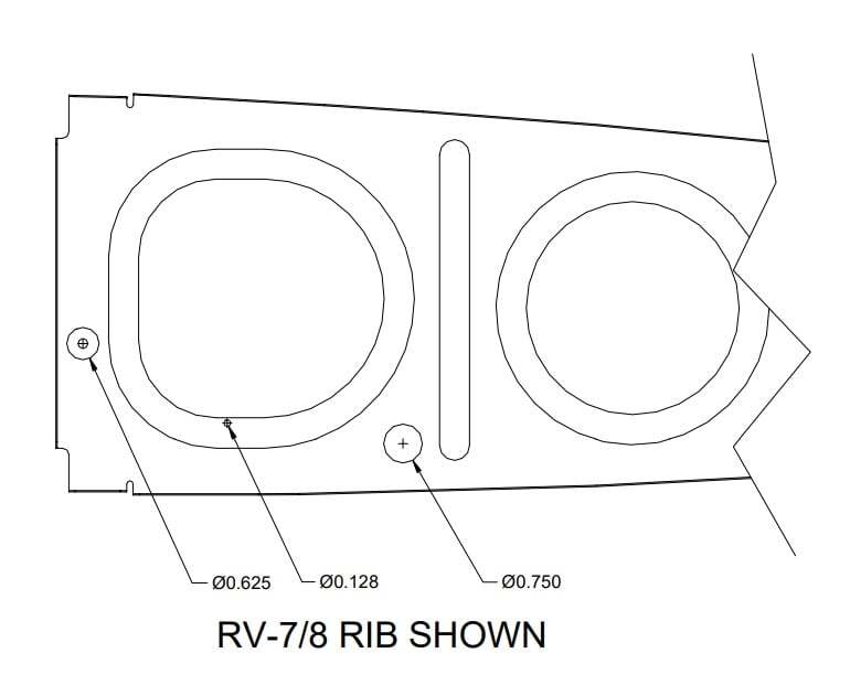
There are a number of installations that require routing of wires and tubes in the wing. These may include nav lights, strobe lights, landing lights, heated pitot, nav antenna, autopilot, AOA and maybe a stall warning device. Listed here, in no particular preference, are some ways to run wires and tubing through the wing ribs.
1. The tooling holes in the ribs may be drilled to a maximum of 5/8” and plastic Bushings SB625-7 installed. These bushings have a 7/16” inside diameter and should be adequate for most needs. Of course, smaller bushings can also be used.
2. An additional hole may be drilled in the lower 1/3 of the rib between the large lightening hole and the next one aft. This hole may be up to 3/4” diameter to accommodate our wiring conduit (DUCT NT 5/8-50) or Bushing SB750-10 (5/8” I.D.). The conduit is light and flexible. It’s .810 “ outside diameter means that when snapped into place, the corrugations hold it from slipping out. If using the conduit, a dab of fuel tank sealant or RTV should be put on the conduit at each rib to prevent the conduit from being cut through over time from vibrations.
3. You can drill a small hole, #30 will do, near the edge of each lightening hole in the rib and use a cable tie to tie either wire or conduit in place. Be sure to protect the wire from chafing on the lightening holes. Hint: To get a pull string through the conduit, tie the string to a cotton ball and blow it through with an air gun or suck it with a vacuum. In all instances, make sure that there is no interference with the aileron bellcrank or control rods.