
This article collects Builder Technical Support answers on engine selection and firewall forward installation.
Inverted oil and fuel systems
If you ordered a standard engine and want inverted-flight capability, plan on a third-party inverted oil system such as the Christen / Raven inverted oil system. Van's does not supply an inverted oil kit; contact the inverted-system vendor directly to spec the parts for your specific engine and airframe combination.
For inverted fuel feed, the wing tanks and stock fuel pickups on most RV airframes will not deliver fuel in sustained inverted flight. A flop-tube (flexible fuel pickup) installation is required in the tank you intend to draw from while inverted. If you are still building, install the flop tube before closing the tank.
RV-12 Rotax 912 / 912iS Builder Questions
This article addresses the most common questions Builder Tech Support gets about Rotax 912 and 912iS installations on the RV-12 and RV-12iS - torque specs, BUDS diagnostics, service letter applicability, and running the engine for ground checks.
Rotax 916 on the RV-9?
Van's has not announced a Rotax 916 installation on the RV-9. The RV-12 is the only Rotax-powered model in the Van's lineup; the RV-9 uses Lycoming variants. Contact Van's directly for any roadmap inquiries.
Rotax BUDS won't connect
If the BUDS dongle won't connect to the Rotax ECU through the 25-pin HIC connector, you can use the 9-pin maintenance port instead. Swap pins 2 and 7 at the DSUB9 maintenance port — that's the CAN bus pin pair — and BUDS should connect. This is the easier-access alternative to working at the HIC connector.
Missing FWF kit bags
Inventory your FWF kit against the packing list as soon as it arrives. If you find missing bags (for example, 626-1, 627-1) or short-counted items, contact Builder Tech Support with your build number, the bag numbers, and a photo of the packing list. Replacement bags ship out separately.
Battery wiring (ES LWH-P10, P14, P25)
Some battery wires shown on FWF detail prints are not always pre-packaged. Confirm against your packing list; missing wires can be ordered through the Parts and Accessories team.
For case-specific FWF questions, contact Van's Builder Tech Support with your builder number, the affected plans page, and photos.
Overview
The Lycoming IO-390-EXP119 is the most common engine on the RV-14 and is also installed on some RV-8 projects. This article covers the questions Builder Tech Support sees most often about the IO-390-EXP119 firewall forward installation.
Engine lifting
The IO-390-EXP119 typically ships with a single lifting hook installed on the case. A single lifting point is sufficient to remove the engine from the crate and place it on the hoist. If you have concerns about your specific engine, contact Lycoming to confirm the lifting procedure for your serial number.
Hardware shortages
If you find missing hardware in your IO-390 FWF kit (for example, only one C01430 instead of two, or missing cable attach hardware), contact Builder Tech Support. Documented kit shortages are typically resolved by shipping the missing hardware bag at no charge.
Related sections
- Section 47-49 (firewall forward)
- Rotax 912iS Installation Manual
- Current Rotax Service Bulletins (rotax-owner.com)
Information to Include With FWF Tickets
- Builder number and aircraft model.
- Engine model.
- FWF kit order number.
- Photos with enough context to identify the assembly.
- Plans page or drawing number where the question originates.
What you still have to do
Final assembly, control surfaces, systems installation (wiring, fuel, brakes), firewall forward, and finishing work remain the builder's responsibility. The QB kit accelerates the structural assembly steps but does not eliminate them.
Overview
The RV-10 is Van's four-place, fixed-gear cross-country airplane. It mixes traditional aluminum airframe work with significant composite components and a Lycoming IO-540 up front. This article covers the recurring questions builders bring to support.
Where to go next
For composite technique, EAA SportAir composite workshops. For FWF-specific questions, see Lycoming's installation manuals and the Van's RV-10 builder forum on VAF. For SBs and SLs, check My Aircraft.
Overview
Engine selection and firewall-forward (FWF) configuration generates a steady stream of questions to Builder Tech Support. This article summarizes the most common situations and how we typically advise builders.
Hot-start issues and sniffle valve location
On the IO-360-M1B, the sniffle valve is mounted in the center of the sump. In a tailwheel installation, fuel can pool aft of the sniffle valve, contributing to hot-start difficulty. Lycoming offers different sump configurations; if this is causing you persistent problems, contact Lycoming directly for sump options - Van's FWF kits are configured around the standard part.
Related references
- Service Letter SL-00019 (SL 19-04-30)
- RV-7/7A Section 14 - Weight and Balance, Rev 2
- Part: F-601A firewall (call to order)
If you are working a damage repair or a non-standard engine configuration, contact Van's Builder Tech Support with photos and your engine accessory list for case-specific guidance.
RV-7 Firewall Forward: Common Install Questions
The firewall forward (FWF) area on the RV-7/7A is where builders encounter the most cross-system integration questions. This article addresses the items Builder Support sees most often.
Fire sleeve parts (FF-00086A/B on RV-14)
FF-00086A and FF-00086B fire sleeve parts are not always on the FWF or Finish kit packing list. If they're missing, contact Builder Tech Support — they can confirm whether the parts ship separately or whether your kit needs a replacement.
Overview
The RV-14 and RV-14A are Van's two-place side-by-side, designed around the IO-390 and matched-hole construction. The -14 is a tailwheel; the -14A is a nosewheel. This article covers the most common build questions and known issues.
WD-1201 nose gear leg replacement (SB 19-08-26)
This is a related but separate SB. The nose gear leg you need is determined by whether the top two engine-mount-bolt holes have already been drilled. If you haven't drilled those holes, contact Builder Tech Support so they can confirm the correct part number.
Who to contact
- QB Liaison / Builder Support - for QB-specific questions, inspection scope, and compliance.
- Parts Order Desk - for replacement parts (including QB-assembled subassemblies if available).
- Lockwood Aviation or California Power Systems - for Rotax engine accessories not sold by Van's.
Van's Tech Q&A: Horsepower Limits: Why not a turbocharged/higher horsepower engine?
Copied from Van's Aircraft Tech Q&A on 2026-10-01. Source: Horsepower Limits: Why not a turbocharged/higher horsepower engine?.
Official PDF: hp_limts.pdf (5 pages). If the viewer below does not load, open the PDF with this link.
Text of the PDF
Copied word for word from the PDF. Figures, drawings and table layouts are in the PDF above.
FLYING HIGH AND FAST
ANOTHER REASON WHY MORE POWER IS NOT ALWAYS A GOOD THING
KEN KRUEGER
While talking with potential RV-10 builders (although the concepts are the same for any airplane), the subject of turbocharged and/or turbine engine installation occasionally comes up. And why not? The idea of maintaining power at high altitudes is very appealing. With the gain in true airspeed inherent in high altitudes and the additional power, you could go very fast, very economically. While turbines are probably not a realistic choice for an RV-10, turbochargers seem easy enough. They’ve been used on enough airplanes and cars to become a familiar part of our mechanical world. The concept of turbo-normalizing is even more attractive. In this case, the turbo merely replaces the air density lost through increasing altitude, so, while the engine can maintain rated power as it climbs, it is never asked to produce more power at low altitudes. The pilot gets the best of both – no extra strain on the engine down low, and more power up high.
Density Altitude / TAS if indicator reads 230 mph
- Density Altitude 0: TAS 230
- Density Altitude 4000: TAS 244.1
- Density Altitude 8000: TAS 259.4
- Density Altitude 12000: TAS 276.3
- Density Altitude 16000: TAS 294.8
- Density Altitude 20000: TAS 315.1
- Density Altitude 24000: TAS 337.6
If you can hold Indicated Airspeed constant, True Airspeed will increase dramatically with altitude.
Why isn’t every piston airplane turbo-normalized? This is a good place to remember Robert Heinlein’s wonderful acronym: TANSTAAFL. There Ain’t No Such Thing As A Free Lunch. As attractive as it appears at first, there are several mechanical arguments against turbocharging airplanes. One of the biggest is heat. If the engine is making full rated power, it must reject a certain amount of heat to stay with operating limits. This is exacerbated by the fact that compressing air makes it hotter. This is manageable if the airplane is in the lower atmosphere where there is plenty of cooling air, but if the engine is operating in very thin high-altitude air, there is a lot less mass to absorb heat. Soon cylinder head temperatures are beyond limits and oil is cooking. But these are mechanical details and people can devise mechanical solutions. They may be heavy, complicated and expensive, but they work.
No, the real problem is not mechanical. The real danger is exceeding the Never Exceed Speed, noted as Vne.
Many pilots assume that operating at high altitude (greater than 12,500 ft, say), even with the increased power supplied by a turbocharger, will not be a problem if the mechanical problems are solved. Sure, they can go faster, but not so much faster that they exceed the limitations marked in living color on the airspeed indicator. How, they ask with apparently perfect logic, can the airplane be exceeding Vne if the needle is in the green arc?
Because the airspeed indicator is The Gauge That Lies. Despite its name, an airspeed indicator does not measure speed. It measures “q” – dynamic pressure caused by packing air molecules into a tube. Now, several limiting speeds like stall speed (bottom of the green and white arcs), gust loads (top of the green arc), and maneuvering speed (blue line) are also functions of q, so they may be read directly off the dial. In these cases, the logic is true.
This logic is NOT true for the very important red line at the top of the yellow arc. Here’s why:
Consider an aircraft flying in smooth air at cruise speed. The aircraft structure is then slightly disturbed (such as by turbulence). In response, the aircraft structure will oscillate with amplitude decreasing until the oscillation stops altogether. This dynamically stable response is due to damping acting on the system, either from the aircraft structure and/or air. If the cruise speed is incrementally increased there will be a particular speed at which the amplitude of structural oscillation will remain constant. The speed at which constant amplitude oscillation can be first maintained is defined as the “critical flutter speed”, or more generically “flutter speed”. Flutter is almost a pretty word. You’d associate it with butterflies and silk handkerchiefs. But in the engineering sense, it can be highly destructive. Once flutter has started, the amplitude may quickly become so large that a structure will disintegrate, literally shaken to pieces.
TURBO-NORMALIZED ENGINE DEVELOPING 75% POWER TO 24,000’
- Density Altitude 0: TAS 187.3; IAS 187.3; Flutter Margin TAS 42.7; Flutter Margin IAS 42.7
- Density Altitude 4000: TAS 194.9; IAS 183.7; Flutter Margin TAS 35.1; Flutter Margin IAS 46.3
- Density Altitude 8000: TAS 203; IAS 180; Flutter Margin TAS 27; Flutter Margin IAS 50
- Density Altitude 12000: TAS 211.7; IAS 176.3; Flutter Margin TAS 18.3; Flutter Margin IAS 53.7
- Density Altitude 16000: TAS 221; IAS 172.4; Flutter Margin TAS 9; Flutter Margin IAS 57.6
- Density Altitude 20000: TAS 231; IAS 168.6; Flutter Margin TAS -1; Flutter Margin IAS 61.4
- Density Altitude 24000: TAS 242; IAS 164.9; Flutter Margin TAS -12; Flutter Margin IAS 65.1
If you installed a turbo-normalized engine that could maintain 75% of 260 hp (195 hp) up to 24,000 feet, the flutter margins will go negative at 20,000…even though the airspeed indicator will show an indicated airspeed well below the red line.
TURBO-NORMALIZED ENGINE DEVELOPING 260 HP TO 24,000’
- Density Altitude 0: TAS 206.2; IAS 206.2; Flutter Margin TAS 23.8; Flutter Margin-IAS 23.8
- Density Altitude 4000: TAS 214.5; IAS 202.1; Flutter Margin TAS 15.5; Flutter Margin-IAS 27.9
- Density Altitude 8000: TAS 223.4; IAS 198.1; Flutter Margin TAS 6.6; Flutter Margin-IAS 31.9
- Density Altitude 12000: TAS 232.9; IAS 193.9; Flutter Margin TAS -2.9; Flutter Margin-IAS 36.1
- Density Altitude 16000: TAS 243.2; IAS 189.8; Flutter Margin TAS -13.2; Flutter Margin-IAS 40.2
- Density Altitude 20000: TAS 254.3; IAS 185.6; Flutter Margin TAS -24.3; Flutter Margin-IAS 44.4
- Density Altitude 24000: TAS 266.3; IAS 181.4; Flutter Margin TAS -36.3; Flutter Margin-IAS 48.6
With an 260 hp engine capable of maintaining rated power up to 24,000 feet, the flutter margin goes negative somewhere below 12,000’.
Remember, as the airplane climbs, there are fewer air molecules and less air pressure, so the needle on The Gauge That Lies reads a lower speed, even though the airplane is actually going just as fast. That’s why True airspeed is faster than Indicated. But flutter does not depend on Indicated Air Speed/dynamic pressure. It is directly related to True Air Speed — the velocity of the air passing by the airframe. The velocity of the excitation force is the prime concern, not the magnitude. It is very possible to exceed this critical “flutter speed” without encountering flutter if there is no initial disturbance. But if the critical flutter speed is exceeded and then a disturbance is encountered, the aircraft structure will begin to oscillate in response to the velocity of the passing air. This is not a typical resonance, where either increasing or decreasing the speed will move the aircraft away from the critical frequency and the vibration will stop on its own. Going faster merely pumps more energy into the system, increasing the amplitude of the flutter. Go faster, flutter harder. Only going slower and lowering the velocity of the air over the airframe will solve the problem.
You’ve probably seen film of the collapse of the Tacoma Narrows Bridge. Built before the aerodynamics of bridges was fully understood, this bridge could probably have withstood the dynamic pressures of a hurricane. But one day, the wind speed was just right – about 42 mph -- to match the natural flutter frequency of the bridge. The bridge started moving, undulating more and more until the whole structure collapsed. There’s still hundreds of tons of concrete and twisted steel out there at the bottom of the bay. The slow writhing of the bridge makes good video, but when flutter occurs in an airplane, destructive failure can be reached at a speed that human senses would detect as a sudden explosion, rather than a vibration. There is no warning, no time to react, certainly no time to slow down.
RVs are designed presuming the installation of naturally aspirated engines (and pilots). Van’s flutter analysis is conservative, but not so conservative as to allow for the true airspeeds that might occur using an engine that can develop 75% of rated power up to altitudes of 20,000 feet or more. The projected performance of a turbo-normalized RV-10 is listed in the tables.
Interestingly, airplanes without engines – let alone engines with turbochargers -- can encounter the same dangers. Sailplanes often fly at quite high altitudes. Those long, long wings tend to be flexible structures which makes them, potentially, quite susceptible to flutter. Sailplanes may not have engines, but they certainly have the equivalent of a lot of power in the Earth’s gravity. They also have very little drag. The combination means that they can accelerate very quickly indeed. A sailplane pilot who points the nose down at altitude could find himself in a grave situation very quickly. It is not uncommon to see charts in sailplane cockpits correlating the Vne to indicated airspeed. Here’s one we saw at SunNFun on the panel of a Pipistrel Sinus motorglider:
PIPISTREL SINUS
- Density Altitude 0: VNE (KIAS) 122
- Density Altitude 3300: VNE (KIAS) 116
- Density Altitude 6500: VNE (KIAS) 111
- Density Altitude 10000: VNE (KIAS) 105
- Density Altitude 13000: VNE (KIAS) 100
- Density Altitude 16500: VNE (KIAS) 95
- Density Altitude 19700: VNE (KIAS) 90
- Density Altitude 23000: VNE (KIAS) 85
- Density Altitude 26300: VNE (KIAS) 80
As you can see from our charts and Pipistrel’s, the margin of safety narrows with altitude, and actually goes negative in some cases. A negative margin of safety is not considered desirable by passengers or insurance companies. Pilots, too, although they are superior beings with greater intellectual capacity, should be concerned. Superior intellect hits the earth just as hard, although it tends to be more surprised when it happens.
If you must hurtle through Mother Nature’s atmosphere at a speed higher than the Vne of the RV-10, it would be best if you found another airplane to do it in. Preferably one designed for the job.
VNE ARTICLE REVISITED
We anticipated – hoped for, actually – a firestorm of discussion over the article in the 6 issue of 2004 concerning Vne. Well, we got a smoldering match head anyway. As I suspected, the idea that a major reason for establishing Vne was based on a True Airspeed number was news to some pilots – it certainly was to me. A couple of correspondents expressed concern, evidently thinking that somehow the safety margins of our airplanes had been narrowed.
They haven’t, as least as long as the airplane is built as designed. Sound engineering backed by ground vibration tests show good flutter margins throughout the planned envelope.
Another caller questioned using True airspeed when FAR Part 23 (the regulations governing certified aircraft) uses indicated airspeed. Again, the answer is about margins. If, for instance, an airplane with a normally aspirated engine is flying above 10,000 feet, the diminishing power will offset the increasing true airspeed by an amount that will make it impossible reach Vne. Whether the pilot is reading true or indicated doesn’t matter – he’s still within the margin of safety. It’s possible that knowing this, the writers of Part 23 decided to keep things simple.
But what if that same airplane has gobs more power available through a turbocharger, or a bigger engine? The designer had to choose a range of powerplants and make some assumptions when he designed the structure and established the Vne. In a certified airplane, that assumption is likely to stay valid. Without a lengthy re-certification process it will be difficult to install a different engine. But of course, we are in the Experimental world, and can put in any engine we choose. The designer can’t possibly provide margins against every possible powerplant. All he can do is tell people what he had in mind and hope those who, inevitably, choose to ignore him don’t die.
Now, installing a turbo or a big engine is one way to add power. Another is to align the flight path to intercept some part of a nearby heavenly body the size of, say, Earth. Something that big pulls pretty hard and with the increase in power comes an increase in speed. Which can sneak up on you, as described at right by Sport Aviation (March 2005) cover boy Rob (Smokey) Ray:
I consider myself a semi-experienced pilot, having amassed over 1400 hours in my RV-4, 3000 in the F-16 and many more in other (less fun) airplanes. However, my commute home from Guard duty was a little different today, and I learned something from it.
Smokey Maules Alaska then heads for a lesson in his RV-4.
I was in my very stock 150 hp RV-4, returning to Florida from a weekend of flying F-16s in Alabama. I was cruising at 11,500’ in cool, smooth air. There was only 235 miles to go, but the way ahead was studded with thunderstorms. Passing Thomasville, GA, the storms got closer together, forcing me to fly continuous pylon turns around the mountain-like build-ups reaching far above my altitude. JAX center was kindly giving me updated weather, and between their help and the good visibilities, I was almost enjoying all my zig-zagging around the clouds. Then, rounding one cloud, I saw my gap ahead had narrowed to a needle-sized opening below my altitude. There was blue sky beyond.
I looked up for a couple of seconds to judge the clouds while I executed one 360 degree descending turn like I had done a million times before down in thick air at 5,000’. But this time I felt something different -- a very high frequency vibration. The stick shook in my hand and the entire airframe vibrated like something had come loose. (Symptoms strongly suggesting elevator flutter…ed.) When I looked inside, I found I was 15 degrees nose-low, in a 30 degree right bank going through 10,800’, pulling 2G and the ASI read 185 knots. I immediately reduced power and, gently, rolled wings level. Below 175 knots IAS, the vibration ceased, so I continued through the gap and pressed on for home. I spent a lot of the remaining trip looking back through the bubble canopy to see if the tail was still on. After landing, I pulled the empennage fairing and inspected all the attach points, pushrod, hinges and structure. Not a scratch.
Epilogue: I got on the internet and researched flutter in light airplanes. There were some great articles on the subject. Seems I should have known that at 10,800’ my TAS at 2 degrees Celsius and 185 knots indicated was over 236 knots. That’s over 250 mph or 40 mph above the Vne of the RV-4. Now, I’m a spoiled F-16 pilot – there are no speed restrictions on the F-16. I know my RV-4 pretty well, too, but how many of us know our airplanes above 10,000’? I know that the RV-4 has a Vne for a reason and now I understand why that limit changes with altitude.
There’s a trend these days toward more powerful and faster RVs. Maybe pilots should consider design loads and flutter thresholds before they go there. My experience could have happened to anybody. I was lucky. The next guy may not be.
There’s several lessons to learn here – One: a professional pilot is willing to admit that he didn’t know something, that the lack of knowledge could have hurt him and takes the initiative to do the research and pass on what he’s learned. And two: A professional fighter pilot builds an RV. What kind of RV? A simple, very light, 150 hp RV, that’s what. No huge engine, no masses of heavy equipment. He knows what flies best.
ALL THE PRETTY HORSES
IN WHICH THE TERM “THE ENVELOPE” IS EXPLAINED AND WHY TOO MANY PONIES IN YOUR RV-9A CAN BUY YOU BIG TROUBLE.
We have been asked many times, “why can’t I put a 180 horsepower engine in an RV-9A?”
The short answer is “because it will go too fast.”
But, but…speed is good! Everyone loves speed. Guys spend cubic dollars trying to go faster than their neighbors. RV owners spend evenings in the shop with nail files, laser levels and polishing cloths trying to make their airplanes go faster. There are pin-ups of Dave Anders and Tracy Saylor, right alongside the Snap-on girl, on hangar walls everywhere. Whaddya mean, too fast? How can it be too fast?
Every airplane is designed to handle a certain amount of stress imposed upon its structure. Speed is one factor in imposing stress. While speed itself doesn’t necessarily add significantly to the stress, it can be almost instantly translated into an acceleration (in engineering terms, the word acceleration refers to a change in speed or direction, not just an increase in speed) which does impose a significant stress. If the speed is high enough, the stress may be more than the airframe is designed to withstand.
One of the best ways to visualize this is with a graphic representation called a V-N diagram. The “V” stands for Velocity, or airspeed. It is plotted on the horizontal (“x”) axis. “N” stands for Normal, or a force perpendicular to the direction of flight or Velocity, and is plotted on the “y” or vertical axis. Drawn this way, the V-N diagram looks a bit like an open postal envelope rotated 90º counterclockwise. This resemblance has given rise to phrases like “pushing the envelope” or “exploring the envelope”, or “stretching the envelope.”
But, the word envelope has another meaning, too…it is a boundary, or a line around an area, so these phrases have come to refer to any situation where boundaries are being challenged. “Pushing the envelope,” for an advertising executive, is a figurative term meaning expanding the limits of conventional practice. For a pilot, it is a more concrete term and understanding its true meaning can literally be a matter of life or death.
Starting at 0-0 in the left side of the diagram, a heavy horizontal line represents straight and level, un-accelerated flight producing a steady 1 G “N” load, equal to the weight of the airplane at the moment. Higher than 1 G loads can be applied to the airframe both by loads induced by the pilot through control application, and by “gust loads” induced by air turbulence. For pilot induced G loads, the airplane is rotated or pitched upward so that the wing meets the air at a increased angle of attack, thus increasing the lift and the G load. Gust loads are imposed by moving air meeting the airframe at some vertical velocity. The aircraft retains its attitude (usually level), and the upward moving air (gusts) then increases the wing’s angle of attack, thereby increasing the lift and the G load on the aircraft’s lifting structure (wing). Experience has taught designers to consider gusts with a vertical component (relative to the flight path of the airplane) up to fifty feet per second.
A parabolic curve on the V-N diagram represents the maximum aerodynamic load or lift force that the wing can generate sweeps up from the same point. Since the lifting potential of a wing increases as the square of the velocity, the curve gets progressively steeper with increasing speed. The point where the 1 G line crosses the parabolic curve represents the minimum speed at which the airplane has enough lift to stay in the air. In other words, stall speed in un-accelerated flight.
The maneuvering speed is the speed at which full control application will produce an acceleration that induces a load equal to the design limit load for the airframe. As speed increases above maneuvering speed, the wing is capable of generating lift, as indicated by the parabolic line as it continues upward (or downward for negative G) in swiftly increasing amounts. The airframe, however, is not getting stronger. It is not designed to be capable of withstanding that level of lift or G load. Therefore the envelope limit line must remain horizontal as the value of speed “V” increases until it reaches the redline or Vne speed. In the speed range above maneuvering speed, the pilot becomes the limiting safety factor. He or she must limit control inputs so the design strength of the aircraft is not exceeded.
Here’s a V-N diagram for an RV-9A at gross weight. The white area in the center looks, if you use your imagination, like an envelope, opened and turned sideways. This area is the graphic representation of the loads the RV-9A airframe can safely withstand.
So far we’ve considered loads that fall within the control of the pilot. A pilot can control the airspeed, and how fast the airplane changes direction, and to some degree, weight. But he can’t control the atmosphere. So imagine this… you’re flying your sleek RV-9A, without about half the flat plate area of the airplane you trained in, and because speed is good and cubic inches are better, you’ve ignored the designer’s advice and shoved a 180 in the nose. What the heck, it only weighs 15 pounds more and with that Hartzell wound out it climbs like nothing else on the field. Cruising at 180 mph indicated is pretty fun, too. Everything’s fine until the day when you’re flying under a low overcast and the weather is getting worse and it’s getting dark. You leave the throttle in, despite the low altitude. You’ll burn the extra gas if it gets you home before the deluge hits...yeah, the airspeed needle is up into the yellow, but you’ve seen that lots of times and nothing’s gone wrong. Up ahead is that little ridge that’s always a little bumpy….and suddenly that speed you’ve been so proud of becomes your enemy. Remember when you were taking your pilot training and the instructor told you about those pretty colored arcs on the airspeed indicator? The bottom of the yellow arc was maximum structural cruise in smooth air. (You got the question right on the written, but didn’t worry much about it in real life, because that little underpowered trainer couldn’t force itself into the yellow arc with a Jato bottle strapped to its butt.) But now the needle is edging into that yellow band and that bumpiness is really vertical gusts hitting the airplane. This is bad because the real world is about to prove, once more, that the laws of physics are not repealed for ignorance or wishful thinking.
On the V-N diagram you can see a line labeled “gust”. This is the G load that a given airframe will experience when it encounters a sharp vertical gust of 50 feet per second. As the airspeed increases, the G load increases linearly. When it reaches the design strength of the airframe, this becomes the Maximum Structural Cruise speed (Vc) for that airplane. (At least it does in this case...there are other parameters designers use for defining Vc) In the case of the RV-9A, which is stressed for a Normal Category limit of 3.8 Gs at gross weight, this limit is reached at 180 mph IAS. Not coincidently, that’s the bottom of the yellow arc. Speeds between Vc and Vne (the Never Exceed or “redline”) speed, should only be flown in smooth air conditions, so an unexpected gust won’t result in a load that exceeds design strength. In the scenario above, where does, say, 195 IAS intersect the gust line? Outside the envelope!
We’ve seen that if the aircraft’s speed is great enough and the pilot pulls hard enough on the stick, the structural load limits can be exceeded. Similarly, if the speed is great enough and the aircraft encounters an upward air gust of sufficient velocity, the structural load limits can be exceeded. The end result is the same; a load is imposed on the aircraft structure that is more than it was designed to withstand. Something has to give.
Vne can be established based on a number of factors. One consideration is the speed at which the airframe design limit will not be exceeded when encountering a sharp edge vertical gust of 25 fps. Another is the maximum safe speed at which the airplane can be flown without encountering aerodynamic flutter. The RV-9A Vne was set based on flutter considerations. But in cruising flight, gust loads are the limiting factor. If an engine capable of producing 75% power speeds of over 180 mph is used, design strength could be exceeded.
You might study the envelope and conclude that since speeds between Vc and Vne are permitted in smooth air, you can increase the power and speed, and then only fly in smoother air. This works fine in theory. But when you look at the diagram you can see how much closer to the edges of the envelope you are. In both the graphic and real sense, you are cutting drastically into your margin of safety, because, in reality, we never know for sure where that 50 fps gust is lurking…and the faster you go, the slower that gust can be and still exceed the limits. Fast enough, and a 25 fps gust can bring you down. The FAA, and designers, must assume that the airplane is going to be used in a wide variety of circumstances by a wide variety of pilots. The premise is that the airplane should be safe when flying at 75% power in real atmospheric conditions, not that it be safe only when flown is smooth conditions. The standards are set for good reasons and we don't play Russian Roulette with them. A pilot of an RV-9A who is exceeding structural cruise speed, no matter how carefully and skillfully he flies, is not in control of the critical factors and is putting himself and his passengers at risk. Avoidable risk.
An aerobatic pilot can assume that he is the limiting factor. Because of the strength designed and built into it to withstand aerobatic loads, an aerobatic airplane can easily withstand gust loads at 75% power cruise.
With standard category airplanes of the same power and aerodynamic drag, (assuming that the pilot behaves himself) the load limits are more likely to be reached through excess speed, turbulence, or a combination of the two.
This why we resolutely recommend against any more than 160 hp in the RV-9A. It puts the pilot and his passengers closer to the edge of the envelope, even in what feels like “normal” flying.
This answer seems unsatisfactory for many because "hot rodding" homebuilts is a time-honored tradition. Time-honored or not, it is potentially hazardous. Yes, it can be done "legally" because of the broad freedoms afforded homebuilders. But, in homebuilt airplanes, "legal" (i.e., have an airworthiness certificate), and "safe" (building an airplane that operates within the design envelope) can be vastly different.
Now that you have a better understanding of the design criteria and the potential forces at work, we hope that you will build an airplane that flies well within its envelope.
Van's Tech Q&A: RV-14 Firewall-Forward wrap-around image view
Copied from Van's Aircraft Tech Q&A on 2026-10-01. Source: RV-14 Firewall-Forward wrap-around image view.
The interactive wrap-around view only works on the Van's website: open the RV-14 Firewall-Forward wrap-around image view.
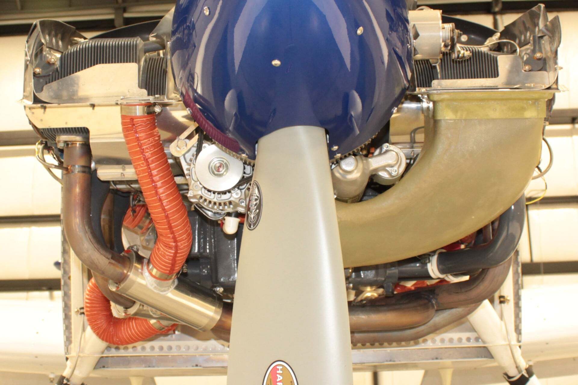
- Title: RV-14 FWF Turntable
- Author: Van's Aircraft
Van's Tech Q&A: RV-14A Firewall-Forward wrap-around image view
Copied from Van's Aircraft Tech Q&A on 2026-10-01. Source: RV-14A Firewall-Forward wrap-around image view.
The interactive wrap-around view only works on the Van's website: open the RV-14A Firewall-Forward wrap-around image view.
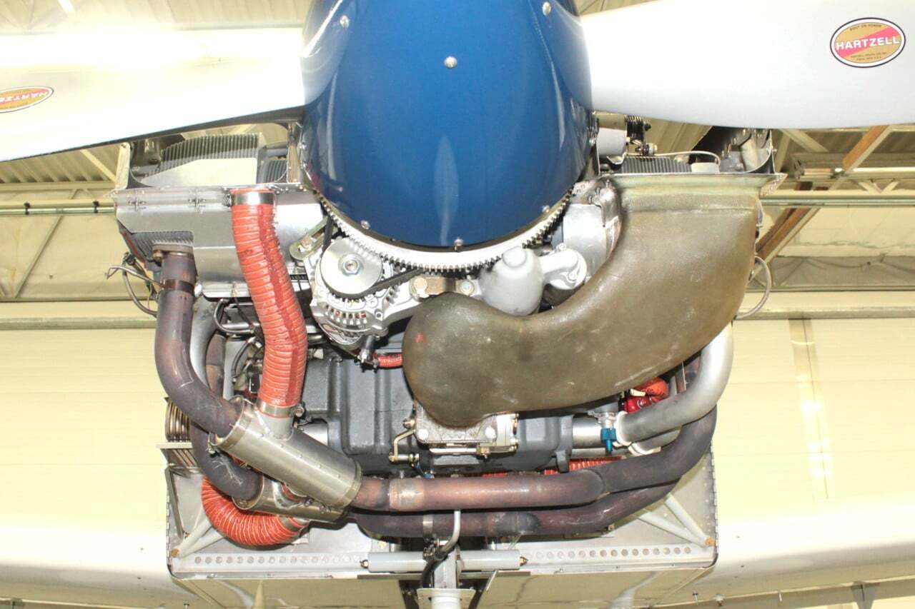
- Title: RV-14A FWF Turntable
- Author: Van's Aircraft